Arduino Mega+ESP, DIP Switches, and Pulling My Hair Out
Date: 4/13/2020 10:37:59 PM
A few months back, I started a custom Smart Thermostat project. Prior to this project, I’d messed around with a few other demo projects, built an ESP/Stepper Motor + Google Assistant Dog Feeder, etc. For the Smart Thermostat, to build upon what I had already learned, I wanted to learn some new fundamentals. Namely, I wanted to:
- Work with a touchscreen shield
- Learn how to code a UI for the touchscreen, and ensure it was responsive
- Figure out the 24VAC to 5VDC conversion to power the thermostat off the furnace rail, instead of a USB wall-wort
- Find some small package, solid state relays that would work with the furnace’s 24VAC lines for heat/cool/fan
- Learn and practice some perfboard prototyping so I can assemble a shield for my sensors, power, and relays
I started the Smart Thermostat project with a run-of-the-mill Arduino Mega. Once I had the above bullet points worked out, it was time to find the perfect Wi-Fi solution. I Googled Arduino Mega with WiFi, and this board grabbed my attention --- it’s a Mega; has an onboard ESP, it’s inexpensive – add to cart!
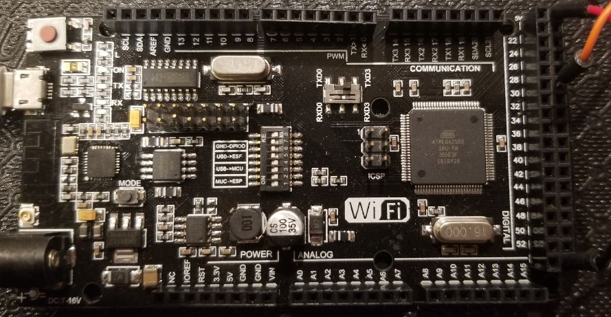
Since the board doesn’t have any model or serial numbers on it, here’s a picture of it:
When I purchased the board, the online store’s description was brief, and I did not notice the DIP switches. After receiving the board, I was disappointed that it did not come with any documentation, drivers or anything. But I figured, no problem! I’ve worked with the Mega now, and I’ve put the ESP8266 through its paces, how hard could this be?
It didn’t take long before I realized I had no clue what I was doing. After copious Googling, I came to realize the following:
- The Mega & ESP are on the same board, but they are definitely two distinct chips: requiring their own sketches.
- DIP switches are scary (*cough* giant PITA), when you don’t know exactly how they’re supposed to be used.
- The Mega & ESP can talk to each other, but it must be done (essentially) over serial prints and reads.
The DIP switch and the RX/TX switch.
First, the RX/TX switch that is near the DIP Switch – honestly, I don’t have the slightest idea what this is for, BUT set it to RXD3/TXD3 – not to RXD0/TXD0. Maybe someone can fill me in, but my high-level understanding is that this is telling the board that the Mega and ESP should talk to each other over Serial3 (check out the sketches to see what I mean).
Next, the DIP switches. This literally took me a week to figure out. The DIP switches basically set the board to a specific mode. Each mode is distinct, and must be set every time you want to perform one of the below operations. Googling around, this was what I found:
- Upload sketch to ESP – 5/6/7 ON, all others OFF
- ESP Debug mode – 5/6 ON, all others OFF (this allows the ESP to output to the Arduino IDE Serial Monitor)
- Upload sketch to Mega – 3/4 ON, all others OFF (this also seems to allow the Mega to output to the Arduino IDE Serial Monitor)
- Production Mode – 1/2 ON, all others OFF ***WRONG, see below***
In some places online, I found that the production mode (aka Mega<->ESP mode), frequently said to have DIP 1/2 ON and the others off. On the surface, this make sense (even the board has a label of MUC->ESP over DIP 1/2). But it wasn’t until I saw Arsh Sekhon’s video (https://www.youtube.com/watch?v=U0Z5rXPQy1Y), that I realized the “Special Solution” I had seen elsewhere on the web was what I needed for “production mode” to allow the Mega & ESP to communicate with each other over serial. I would have not figured this out without Arsh’s video.
To reiterate --- Production Mode needs to be 1/2/3/4 ON, all others off
And just for added clarity, the way this whole thing comes together is like this:
- Create an ESP sketch, set the DIP to 5/6/7, and upload the sketch over USB
- If you want to Serial Monitor the ESP to test your sketch, set the DIP to 5/6
- Create a Mega sketch, set the DIP to 3/4, and upload the sketch over USB
- Set the DIP to 1/2/3/4 and you’re in production mode (allowing the Mega & ESP to talk to each other)
The Sketches
First, let me say that I’m a C#/.NET developer by day, and I’m still learning Arduino and trying to refresh my brain on C++ -- so these sketches are not pretty, but they will at least give you some idea of how I got the Arduino Mega and ESP to talk to each other. By all means, if you see something stupid that I did, don’t hesitate to drop me an email – I’d love to hear from you!
Okay, let’s look at the ESP sketch first. I’ve tried to document the code to make it understandable. Obviously be sure to fill in the appropriate definitions/variables for your setup (e.g. SSID, WiFi Password, etc).
ESP Sketch
https://pastebin.com/igrJtDLD
Arduino Mega Sketch
https://pastebin.com/SVT56cPD
I’m sorry for the poor code pasting. At some point, I will try to get these uploaded to my GitHub (and I'll update this post), but for now I know there are multiple people looking for this example and I just don’t have the time to do more (I’m sorry).
I hope someone will find something interesting, helpful, and even provide me with some feedback on how I can improve it.
Until next time, happy coding and don’t pull out all your hair over undocumented DIP switches.
…and since it’s currently relevant, I wish everyone health and safety during this difficult season of dealing with COVID-19.
PS. Just in case I get the code to GitHub and forget to update this blog post, you can find me at https://github.com/tedkrapf/